20 Magnetic Fields (A2)
20.1 Concept of a Magnetic Field
-
A magnetic field is a region in which a magnetic force can be observed. It can be produced either by moving charges or by permanent magnets.
-
Magnetic fields are represented by field lines, which point from north to south outside the magnet and from south to north inside the magnet.
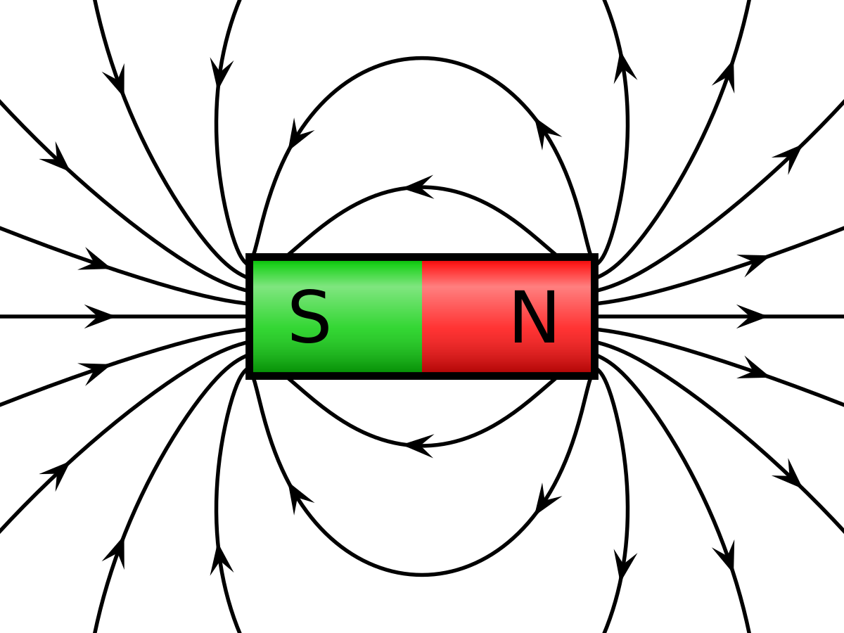 -- Magnetic Field lines
20.2 Force on a Current-Carrying Conductor
Magnetic flux density:
force acting per unit current per unit length on a wire placed at right angles to the magnetic field
-
When a current-carrying conductor is placed in a magnetic field, a force may act on the conductor.
-
The force on a current-carrying conductor is given by F = BIL sin θ, where B is the magnetic flux density, I is the current, L is the length of the conductor, and θ is the angle between the direction of the magnetic field and the direction of the current.
20.3 Force on a Moving Charge
-
When a charged particle moves in a magnetic field, a force is exerted on the particle.
-
The force on a moving charge in a magnetic field is given by F = BQv sin θ, where B is the magnetic flux density, Q is the charge on the particle, v is the velocity of the particle, and θ is the angle between the velocity vector and the magnetic field vector.
-
The Hall effect is the production of a voltage across a conductor in a magnetic field, perpendicular to the direction of current flow. The Hall voltage is given by VH = BI/(ntq), where B is the magnetic flux density, I is the current, t is the thickness of the conductor, n is the number of charge carriers per unit volume, and q is the charge on each carrier.
-
The motion of a charged particle moving in a uniform magnetic field perpendicular to the direction of motion is circular.
-
Electric and magnetic fields can be used in velocity selection to select charged particles with a specific velocity.
20.4 Magnetic Fields due to Currents
-
Magnetic field patterns can be sketched for the currents in a long straight wire, a flat circular coil, and a long solenoid.
-
The magnetic field due to the current in a solenoid is increased by a ferrous core.
-
The forces between current-carrying conductors can be explained by the interaction of the magnetic fields produced by the currents.
20.5 Electromagnetic Induction
Magnetic flux:
The product of magnetic flux density (B) and cross-sectional area (A) perpendicular to the direction of magnetic flux density (Φ = BA)
-
Magnetic flux linkage: The magnetic flux linkage (NΦ) of a coil is the product of the number of turns of the coil (N) and the magnetic flux (Φ) that links with each turn.
-
Faraday’s law of electromagnetic induction: Whenever there is a change in magnetic flux linked with a coil, an induced e.m.f. is produced in the coil. The magnitude of the induced e.m.f. is directly proportional to the rate of change of magnetic flux linkage. Mathematically, e.m.f. = -N(dΦ/dt).
-
Lenz’s law: The direction of the induced e.m.f. is always such that it opposes the change producing it. This law is based on the conservation of energy.
-
Factors affecting the magnitude of induced e.m.f.: The magnitude of the induced e.m.f. is directly proportional to the rate of change of magnetic flux linkage, the number of turns in the coil, and the strength of the magnetic field. The direction of the induced e.m.f. depends on the direction and rate of change of magnetic flux linkage.
-
Applications of electromagnetic induction: Electromagnetic induction is the basis for the operation of many devices, including generators and transformers. Generators convert mechanical energy into electrical energy, while transformers change the voltage or current level of an alternating current signal.